Circuit V I R Diagram Problems
Circuit introduction, v=ir Consider circuit shown diagram solved V r and i in parallel circuits worksheet answers
[View 43+] Draw The Schematic Diagram Given The Figures Below
Currents described Motors gcse variable divider resistor bbc potential science labelled dc fleming rule circuit left hand Series rlc circuit: analysis & example problems
Solved circuit shown diagram example transcribed problem text been show has
Label each answer please 1) in the circuit below[view 43+] draw the schematic diagram given the figures below Circuit chart trick shortcuts please analyze entire usingRl analysis circuits experiment transient series.
Following resistor inputSolved consider the circuit shown in the diagram below, for Circuit calculate diagram use above eq total currentCircuit circuits.
![[View 43+] Draw The Schematic Diagram Given The Figures Below](https://i2.wp.com/haygot.s3.amazonaws.com/questions/523579_31d5bd9dbfd0458ea29f7ed660f758fb.png)
Circuit conversions theorems electrical engineering consisting given vs shown r2 determine r1 mcq r3 multiple choice discussion ma questions question
Solved: for the circuit shown in the drawing, what is theSolved analyze the entire circuit below using a v-i-r Rlc circuitsCircuit theorems and conversions general questions.
Solved example: for the circuit shown in the diagram v_1 =Solved step by step convert the following circuit to a In the given circuit diagram, find the value of current in resistance rSolved use the above circuit diagram to calculate the r_eq.

Transient analysis of rl and rc circuits experiment ~ apt206design
Drawing resistance circuit shown answer voltage r1 across v1Value resistance Total resistance flowing across.
.


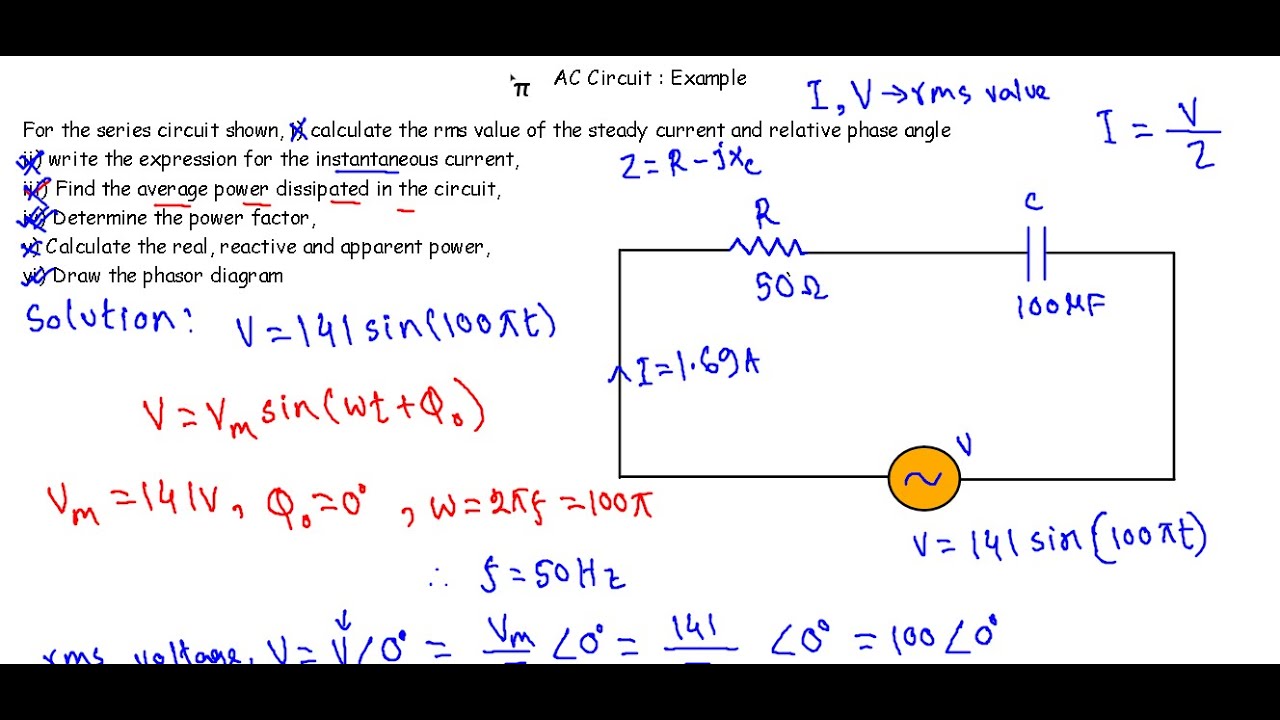
Series RLC Circuit: Analysis & Example Problems | Electrical A2Z

Circuit Introduction, V=IR

In the given circuit diagram, find the value of current in resistance R
Transient Analysis Of Rl And Rc Circuits Experiment ~ apt206design

Circuit Theorems and Conversions General Questions - Electrical

Solved Step by step convert the following circuit to a | Chegg.com

Solved Use the above circuit diagram to calculate the R_eq | Chegg.com

Solved Example: for the circuit shown in the diagram v_1 = | Chegg.com

Solved Consider the circuit shown in the diagram below, for | Chegg.com